This document describes how the data and ecc bits are added to a QRCODE symbol
(The ISO standard description is poor).
The task is
complicated by the way bytes are folded in attempt to disrupt typical data sequences creating unintended
patterns that might confuse symbol recognition software. In fact, after this initial placement is complete,
an
additional process applies a series of masks in turn, and selects the mask that gives the data part the best
random pattern. The mask that was selected is published (twice) in the format information modules.
 Bit Packing Strips.
 Data is added to the symbol starting in the bottom right hand corner and added bit by bit in vertical strips
two bits wide.
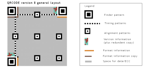
Figure 1 shows how a number of full height strips may be delineated in a symbol. Note: Column 6 does not contain any valid
data positions (in any version) and is excluded. Each "version" increment of the symbol adds an extra 4 modules to the width so, there will
always be an even number of strips.
←
The most significant
bit of the data is added to the module at the
bottom right hand corner of the symbol. This corresponds to the bottom right position
in the rightmost strip. The second bit of the data is added immediately to the left of this
module. This process is repeated in a zigzag pattern in the upwards direction.
The
"preferred" bit placement can be understood by following the path linking all the modules
as shown in
Figure 2, starting at the bottom right hand corner.
If the "preferred" position is not shown as
an "available" data position (i.e because it is occupied by QRCODE "formatting furniture" like
information modules or functions patterns) the next preferred position along the path is selected and the test is repeated. The full height of
symbol is scanned within each two bit strip looking for available data positions before moving on to the next strip.
When there are no futher bit positions available in the strip, the adjacent strip to the left
is selected and the search for
the next available module position continues in the opposite direction. Packing continues to change direction as available positions are are exhausted in each strip,
until every bit of the data/ecc bit sequence has been placed.
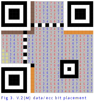
For example, to encode 28 data bytes at "M correction level" the symbol must accomodate a total
of 44 bytes (28 data bytes + 16 ECC bytes). Figure
3 shows how Version 2 of the symbol is used to place a total of 352 bits.
The remaining 7 modules in the symbol
are coded 0 before masking.
|
 |


